For my recent project, I wanted to read signals from the AC (Alternating Current) board to check whether a switch is turned on or off. The signal I wanted was a fairly simple square wave pulse. Whenever an AC switch is turned on or off, the signal can be directly read by an Arduino or any other microcontroller with its digital I/O pins.

To achieve this, I searched the internet to find something to make the job simple and straightforward. I found a few optocoupler-based modules that could do the job, but they were either expensive or very poorly rated by consumers.
This is what it looks like.
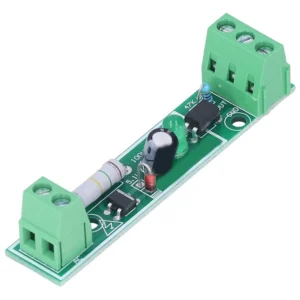
This circuit works perfectly fine. The only problem I have with this product is that it’s very costly. The price is not justified at all. So, I reverse engineered the circuit to find out if it is worth paying $4 – $5 for this product.
Let’s see what we have here.
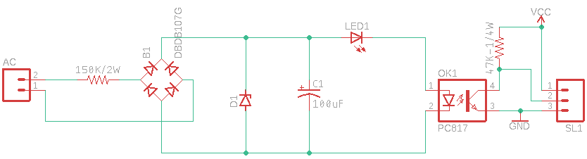
This module is based on the PC817 Optocoupler, Here is the list of parts that this module uses.
| S.No | Part | Quantity | Price |
| 1 | Resistor 150k/2 watt | 1 | $0.037 |
| 2 | Bridge-Rectifier | 1 | $0.051 |
| 3 | Zener Diode | 1 | $0.019 |
| 4 | Electrolytic capacitor 100uF | 1 | $0.024 |
| 5 | Led | 1 | $0.012 |
| 6 | Optocoupler PC817 | 1 | $0.049 |
| 7 | Resistor 47k / ¼ watt | 1 | $0.0032 |
| 8 | Block-Terminals 2 Pin | 1 | $0.049 |
| 9 | Block-Terminals 3 Pin | 1 | $0.061 |
| $0.3052 |
When I figured out how much it would cost me to make it myself, I was totally shocked. It took me just one minute to assemble the entire circuit on a breadboard.
I saved both time and money, and it also provided me with the flexibility to make the circuit according to my requirements.
Let’s make it.
Step 1. Purchasing only the required parts.
| S.No | Part | Quantity |
| 1 | Resistor 150k/2 watt | 1 |
| 2 | Bridge-Rectifier | 1 |
| 3 | Electrolytic capacitor 100uF | 1 |
| 4 | Led | 1 |
| 5 | Optocoupler PC817 | 1 |
| 6 | Resistor ¼ watt | 1 |
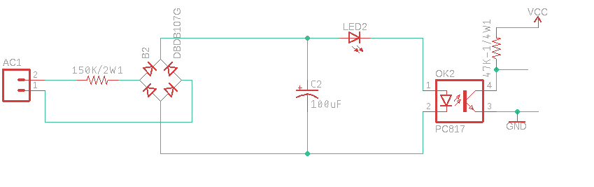
As we don’t require the block terminals for this project, I removed them from the list. We also don’t need the Zener diode since it would never come into play.
Please go ahead and purchase all the necessary components, and we’ll move on to the next step.
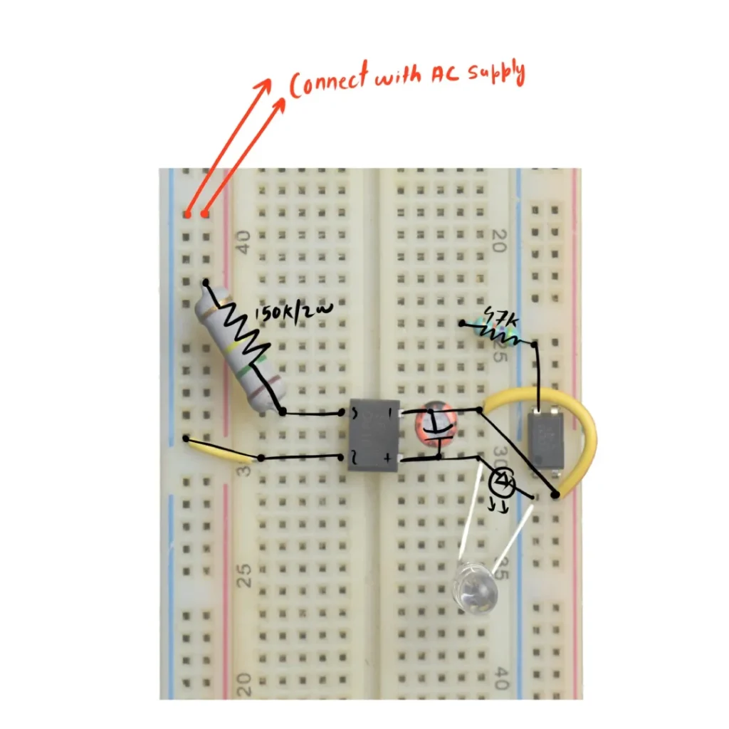
Step 2. The Assembly.
We need a breadboard to start assembling all the pieces together. Just follow the schematic as shown here.
Here is how I placed all the components.
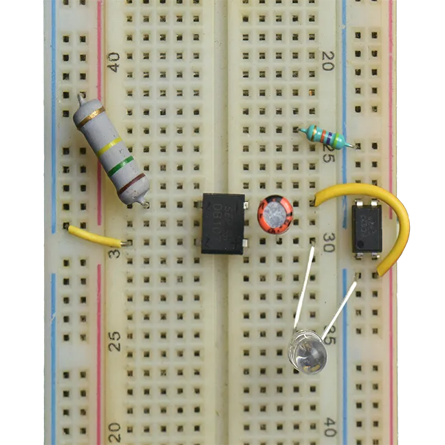
Note: The optocoupler is placed where the power rail separates. Ensure it is not connected anywhere else on the breadboard. Remember, all pins of the optocoupler are isolated from each other.
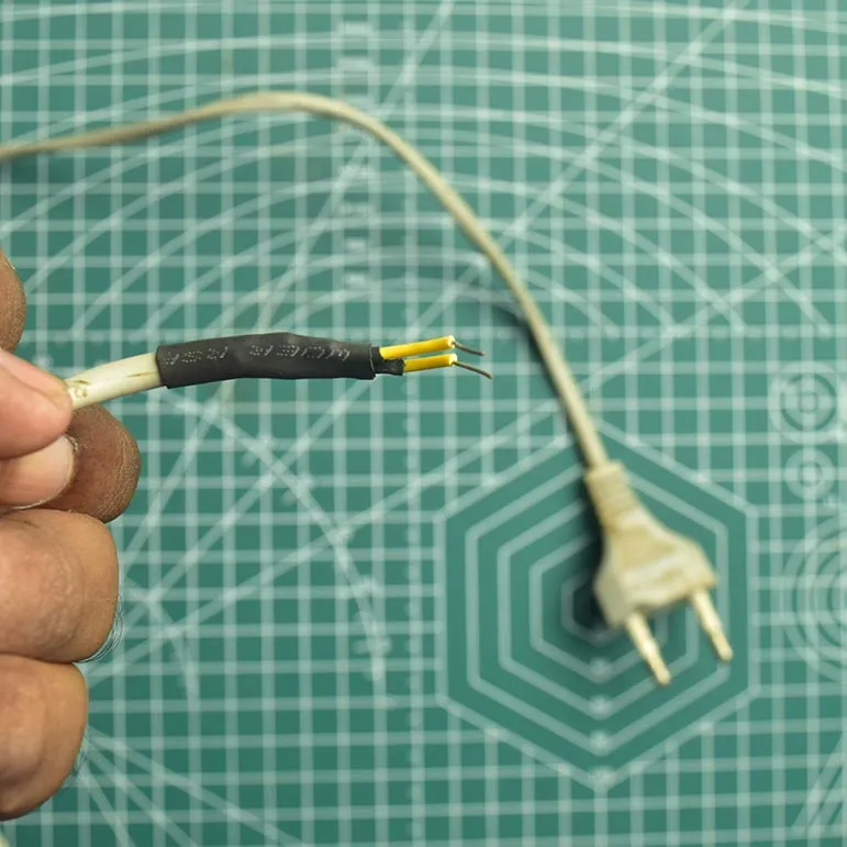
Step 3. The AC(Alternating Current) wire.
Note: If you are working with an AC please make sure to wear proper Current safety gloves. AC is not a joke. Be careful.
The AC standard in our country is 220V at 50Hz. The entire project is based on this current configuration.
I used an old wire for the AC power supply to the breadboard. Additionally, I modified the wire by soldering a single-head wire connector to make it easier to connect to the breadboard.
Step 4. Verifying the board.
Before connecting the Arduino to the final circuit, ensure all connections are properly secured. Once verified, connect the AC supply to the board to check if it functions as intended.
If the board is connected correctly, the led will glow when the AC switch is turned on and vice-versa.
Step 5. Setting up with Arduino
Okay, finally, our circuit is working properly. Now, it’s time to make the final connection with the Arduino. For this project, I’m using the Arduino UNO, but you can use whatever board you prefer. Here’s how you need to connect the circuit to the Arduino.
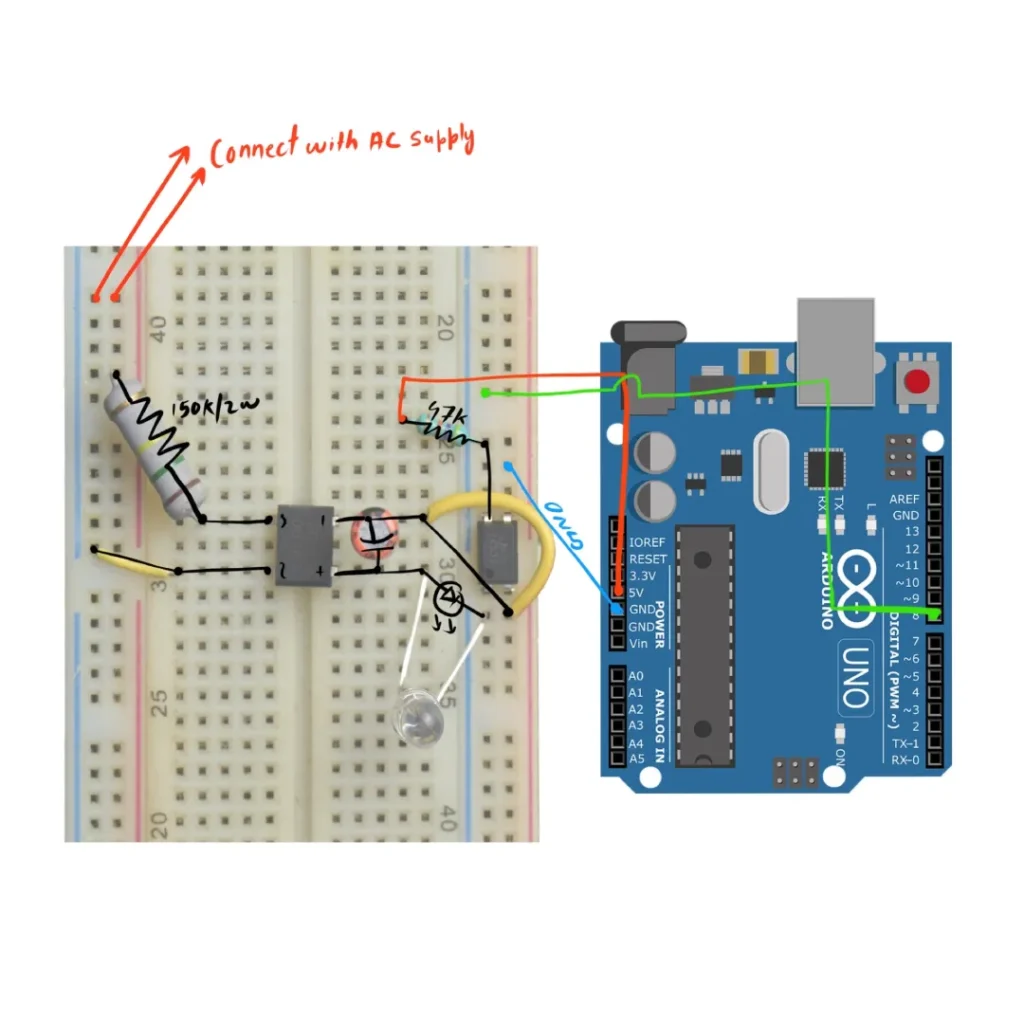
I’m using PIN 8 of the Arduino to read the incoming signals. The circuit is connected in a pull-up configuration. This means if the AC switch is turned off, we’ll receive a high signal on PIN 8, and if the switch is turned on, we’ll receive a low signal. It essentially acts as a ‘NOT’ gate.
Note: Please do check all the connections once again as we are dealing with Alternating Current. Optocoupler isolates both sides but we still need to cross verify it.
Step 6. Some Basic Code (Programming the Arduino Board).
void setup() {

  // put your setup code here, to run once:

pinMode(8,INPUT);

Serial.begin(9600);

}

void loop() {

     // put your main code here, to run repeatedly:

      if(digitalRead(8))

       {

        Serial.println("Switch Is OFF");

        //Do Something Whenever the Switch is turned OFF

       }

       else

       {

        Serial.println("Switch Is ON");

         //Do Something Whenever the Switch is turned On

       }

}
Some extra tips
With a 100uF capacitor, you’ll notice some delay when reading the switching state due to its higher capacitance value. To reduce this delay, I replaced the 100uF capacitor with a 4.7uF capacitor and achieved very good and consistent results. You can also experiment with different capacitor values to achieve results that meet your specific requirements.
Conclusion
If you’re seeking a cost-effective, efficient, and customizable approach for detecting AC switching states, this circuit works perfectly. It’s compatible not only with Arduino but also with other microcontrollers capable of reading digital signals, such as ESP8266, ESP32, Arduino Nano, etc.